555 (timer) circuit capable of controlling loads up to 10 A
Long timers are useful for a variety of applications such as pool filter control, aquarium aeration, greenhouse etc. The device described in this article can be set to a maximum time of 45 hours and has the possibility of being deactivated by external sensors as an important feature. The circuit is capable of controlling loads up to 10 A (1100 W in the 110 V network), and uses low cost components.
The timer we describe in this article has several important features as well as sweeping a range of times that makes it useful in a multitude of practical applications.
Among the main characteristics of the device, we highlight the following:
- Turns on or off an external load at the end of the programmed time;
- Auto-off at end of timing;
- The timing can be interrupted at any time by the signal sent by external sensors;
- Covers a range of 3 minutes to 45 hours;
- Operates on both the 110 V and 220 V mains, depending only on the choice of the transformer.
Since the circuit has an analog time base, the accuracy in the timing depends exclusively on the setting.
- Many are the applications that can be given to the timer like, for example:
- Turning off a television after a certain time, for those who usually sleep and forget the connected device;
- Turning off or switching on balcony lights after a certain set time;
- Switching off appliances that need to be operated for a certain time, such as heaters, air conditioners (provided they require less than 10 A) etc;
- Control of printed circuit boards or exposition of photographic films.
Characteristics
Input / Output Voltage: 110/220 Vac
Low voltage power supply voltage: 12 V
Power consumed: 5 W
Maximum controlled load: 10 A
Timing range: 3 min. at 45 h
Types of input sensors: resistive
Components: 4 Cls and 2 transistors
How it works
The integrated 555 (timer) circuit has been the most used in timer design. However, this component has some "deficiencies" that make it unstable for timings over 30 minutes.
These timings require capacitors of high values, which always have leakages that compromise the accuracy of the timings.
One means of obtaining larger timings, without compromising this feature, but operating at its limit, is the use of dividing circuits.
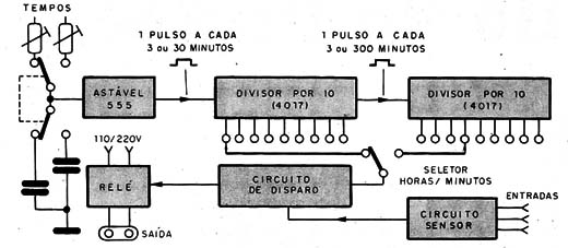
This idea is rightly used in our project, which has the block diagram shown in figure 1.
Figure 1 - Timer block diagram
In this circuit the 555 operates as a very slow oscillator, with a cycle every 3 minutes in the timing position of up to 4 1/2 hours, and every 30 minutes (maximum value) in the position of up to 45 hours.
The adjustment of this cycle will precisely determine the accuracy of the timer, which is also linked to the quality of the components used.
In figure 2 we give the complete diagram of the apparatus.
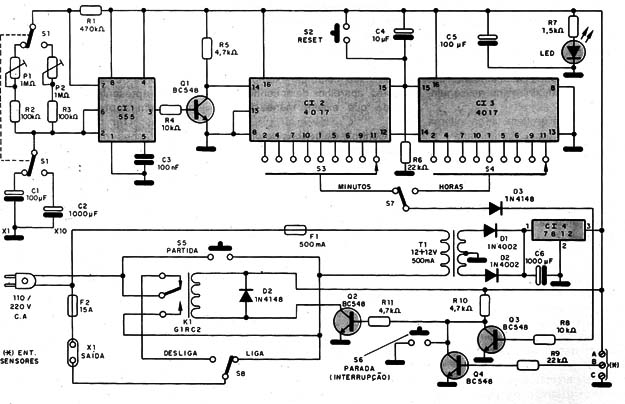
Figure 2 - Timer complete diagram
The pulses generated by the astable 555 are brought to two cascaded cascaded 4017 integrated circuits . These integrated are nothing more than "time extenders" or frequency dividers.
In simpler language we can say that these 4017 circuits count the pulses, distributing them through their outputs according to their number or order of arrival.
In short, the first output being triggered in the "zero" situation (which is ensured by the reset circuit formed by R 6 and C 4 , which is not used in our case), when the first pulse arrives the counter causes the next output, or first output used, go to the high level, and the previous output to the low level.
With the second pulse, the second output used is activated and the previous one is deactivated and so on until the last one.
In the last output, the pulse that deactivates it restarts the cycle by activating the output "zero", as indicated in table 1, and at the same time is applied to a similar step with another 4017.
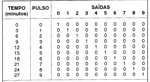
See, then, that if we connect the astable 555 at the input of this counter, since its frequency is 1 pulse every 3 minutes, we will have the outputs of the first 4017 activated at equal intervals, just 3 minutes.
Since the 4017 activation pulses occur at the 555 transition from the high to the low level, an inverter formed by O1 is required to ensure the production of the first pulse only after 3 minutes of the power supply.
If the switch S 1 is in the position that connects the capacitor of 1 000 μF we will have the maximum range, and the pulses will be produced at the rate of 1 every 30 minutes.
In the first integrated, then, according to the position of switch S 3 we will have timings of up to 27 minutes (for S 1 in the 3 minutes position) or 270 minutes (for S 1 in the 30 minute position).
If we now consider the last output of the first 4017, we see that a pulse will be produced every 30 minutes or every 300 minutes, according to the position of S 1 .
This pulse, taken from the reset output, serves to form an operating cycle of the second integrated 4017.
In the second 4017 we have the possibility of activating 9 outputs, with the difference that the intervals will be half an hour or 300 minutes, depending on the position of the S 1 switch .
We obtain in this integrated circuit the maximum delay of 4.5 to 45 hours. See then that the choice of timing intervals can be made in one or another integrated.
The time selection switches are connected to the relay drive circuit.
In this circuit, the relay is kept energized until the control pulse coming from the integrated circuit turns it off.
This is accomplished with the aid of two transistors, and has an important purpose: the relay held on for the chosen time interval also controls the power supply of the timer circuit itself, so that, after the desired time has elapsed, the relay opens its contacts also turns off the timer power.
If the reverse were done, by energizing the relay at the end of the timing, we would have to keep the power supply even after the timing has expired.
As indicated in the introduction, the timer applications are only limited by the maximum current controlled by the relay, we indicate in the design a relay of 10 A, which means approximately 1 100 W in the 110 V network and 2 200 W in the 220 V network.
For larger loads, a second relay controlled by the first can be used, or even the original relay is changed. The user should pay particular attention to this condition if he controls high consumption appliances such as air conditioners.
The printed circuit board for the assembly is shown in figure 3.
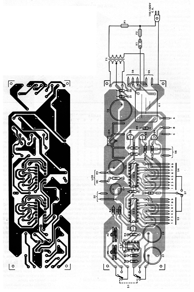
Figure 3 - Mounting plate
The integrated circuits must be mounted in sockets, and CI4 must be fitted with a small heat radiator.
The diodes, as well as the transistors, admit equivalents.
The transformer shall have primary winding according to the local and secondary grid of 12 + 12 V with at least 500 mA of current.
The indicated relay has a 10 A reversible contact, but equivalent relays can be used, with currents depending on the intended application.
In case of using another relay, a change in the layout of the printed circuit board must be made.
The S 1 key is 2 poles x 2 positions, serving for selection of tracks.
S 2 , S 5 and S 6 are pressure switches of type NA, (normally open).
S 3 and S., are 1-pole x 9-way rotary keys. As the type of 10 positions is easier to find, it can be used by leaving the last position free.
The key S 7 , as well as S 8 , is 1-pole x 2-position. Special attention should be given to S 8 , which must withstand the load current, ie up to 10 A.
The Trimmers P 1 and P 2 are common, but if you want a lot of precision in adjustment can use the multi -turn types, of equal value, just by changing the board layout.
The circuit uses two fuses, one to protect the timer and the other to install the powered device. Observe the values and be careful not to change them at the time of installation.
ADJUSTMENTS AND USE
The adjustment requires a little patience, especially in the longer timing. Set the S 3 and S 7 switches to the minimum timing (see panel suggestion in figure 4).
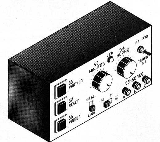
Figure 4 - Panel suggestion
S 1 must be at the minimum timing, which places C 4 in the circuit. By pressing S 5 the relay must be docked, to switch off after a few minutes.
Press S 5 for a new start, and with this procedure, timing the time elapsed between closing the relay contacts and turning them off, set P 4 so that the time obtained is 3 minutes.
Now (with great patience!) Set the S 1 switch to the position that connects C 2 and set P 2 to have 30 minute cycles. Remember that precision of these adjustments will depend on the accuracy of the other scales.
Try larger scales to see if trimpots need new adjustments.
To use the timer we must know the functions of the controls, which are:
S 1 - Selects the time range: maximum of 4.5 or 45 hours;
S 3 - Restarts the device, ie returns the count to zero, at any time of the delay;
S 3 and S 4 - Select the times on the two possible scales;
S 5 - Turns on the unit, starting the timer;
S 6 - interrupts the timing by switching off the appliance;
S 7 - Select which of the timings, S 3 (minutes) or S 4 (hours), is being used;
S 8 - Selects the mode of operation of the relay: if it turns the external load on or off at the end of the time delay.
An example usage procedure is given below: Let us assume that we wish to turn off a television after 2 ½ hours.
a) We connect the timer plug to the mains (outlet):
b) Connect the TV plug to X 4 .
c) We put S 3 in the mode that switches off at the end of the timing.
d) We put S 7 in the position "hours".
e) We put S 4 in position x1.
f) Set S 4 to the position corresponding to 2 and a half hours (5 positions to the right, each of half an hour).
g) Press the pressure switch S 5 , which starts the timing.
At this point, the relay trips and the LED lights up.
h) Simply turn on the TV and tune to the desired channel. At the end of the timer, the timer and TV will turn off automatically.
To use the input sensors an interesting idea is shown in figure 5.
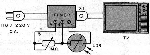
Figure 5 - Using an LDR as a sensor
With this setting, if you sleep and someone enters your room, turning off the light, the TV and the timer will stop the timing, turning off automatically.
If your timer is near a lamp or receiving its illumination, if you turn it off the timing is interrupted and everything off.
Other types of sensors can be used to interrupt timing and even remote controls, as shown in Figure 6.
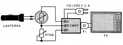
Figure 6 - Flashlight as remote control
Semiconductors:
CI1 - 555 - integrated circuit timer
Cl2, Cl3 - 4017 - integrated circuits CMOS
CI4, - 7812 - Voltage regulator integrated circuit
Q 1 , Q 2 . Q 3 , Q 4 - BC 5 48 or NPN equivalents of general purpose.
D 1 , D 2 - 1N4002 - silicon rectifier diodes
D 3 , D 4 - 1N4148 - silicon diodes of general use
LED - common red LED
Resistors (1/8 W, 5%):
R 1 - 470 kΩ
R 2 , R 3 - 100 kΩ
R 4 , R 8 - 10 kΩ
R 5 , R 1 0 R 1 1 to 4.7 k Ω
R 6 , R 9 - 22 kΩ
R 7 - 1.5 kΩ
P 1 , P 2 - 1 M Ω trimpots - see text
Capacitors:
C 1 , C 5 - 100 μF - 16 V electrolytic
C 2 - 1000 μF - 16 V electrolytic
C 3 - 100 nF - polyester or ceramic
C 4 - 10 μF - 16 V electrolytic
C 6 - 1000 μF - 25 V electrolytic
Several:
S 1 - 2-pole wrench x 2 positions
S 2 . S 5 , S 6 - Pressure switches NA
S 3 , S 4 - 1-pole x 9-way rotary switches
S 7 , S 8 - 1-pole x 2-way sliding wrenches
T 1 - Transformer with primary according to the supply and secondary network of 12 + 12 V x 500 mA
K 1 - 12 V Relay
X 1 - Power outlet
F2 - 500 mA fuse
F2 - 15 amp fuse
Printed circuit board, mounting box, power cable, brackets for fuses, wires, soldering etc.
The timer we describe in this article has several important features as well as sweeping a range of times that makes it useful in a multitude of practical applications.
Among the main characteristics of the device, we highlight the following:
- Turns on or off an external load at the end of the programmed time;
- Auto-off at end of timing;
- The timing can be interrupted at any time by the signal sent by external sensors;
- Covers a range of 3 minutes to 45 hours;
- Operates on both the 110 V and 220 V mains, depending only on the choice of the transformer.
Since the circuit has an analog time base, the accuracy in the timing depends exclusively on the setting.
- Many are the applications that can be given to the timer like, for example:
- Turning off a television after a certain time, for those who usually sleep and forget the connected device;
- Turning off or switching on balcony lights after a certain set time;
- Switching off appliances that need to be operated for a certain time, such as heaters, air conditioners (provided they require less than 10 A) etc;
- Control of printed circuit boards or exposition of photographic films.
Characteristics
Input / Output Voltage: 110/220 Vac
Low voltage power supply voltage: 12 V
Power consumed: 5 W
Maximum controlled load: 10 A
Timing range: 3 min. at 45 h
Types of input sensors: resistive
Components: 4 Cls and 2 transistors
How it works
The integrated 555 (timer) circuit has been the most used in timer design. However, this component has some "deficiencies" that make it unstable for timings over 30 minutes.
These timings require capacitors of high values, which always have leakages that compromise the accuracy of the timings.
One means of obtaining larger timings, without compromising this feature, but operating at its limit, is the use of dividing circuits.
This idea is rightly used in our project, which has the block diagram shown in figure 1.
Figure 1 - Timer block diagram
In this circuit the 555 operates as a very slow oscillator, with a cycle every 3 minutes in the timing position of up to 4 1/2 hours, and every 30 minutes (maximum value) in the position of up to 45 hours.
The adjustment of this cycle will precisely determine the accuracy of the timer, which is also linked to the quality of the components used.
In figure 2 we give the complete diagram of the apparatus.
Figure 2 - Timer complete diagram
The pulses generated by the astable 555 are brought to two cascaded cascaded 4017 integrated circuits . These integrated are nothing more than "time extenders" or frequency dividers.
In simpler language we can say that these 4017 circuits count the pulses, distributing them through their outputs according to their number or order of arrival.
In short, the first output being triggered in the "zero" situation (which is ensured by the reset circuit formed by R 6 and C 4 , which is not used in our case), when the first pulse arrives the counter causes the next output, or first output used, go to the high level, and the previous output to the low level.
With the second pulse, the second output used is activated and the previous one is deactivated and so on until the last one.
In the last output, the pulse that deactivates it restarts the cycle by activating the output "zero", as indicated in table 1, and at the same time is applied to a similar step with another 4017.
See, then, that if we connect the astable 555 at the input of this counter, since its frequency is 1 pulse every 3 minutes, we will have the outputs of the first 4017 activated at equal intervals, just 3 minutes.
Since the 4017 activation pulses occur at the 555 transition from the high to the low level, an inverter formed by O1 is required to ensure the production of the first pulse only after 3 minutes of the power supply.
If the switch S 1 is in the position that connects the capacitor of 1 000 μF we will have the maximum range, and the pulses will be produced at the rate of 1 every 30 minutes.
In the first integrated, then, according to the position of switch S 3 we will have timings of up to 27 minutes (for S 1 in the 3 minutes position) or 270 minutes (for S 1 in the 30 minute position).
If we now consider the last output of the first 4017, we see that a pulse will be produced every 30 minutes or every 300 minutes, according to the position of S 1 .
This pulse, taken from the reset output, serves to form an operating cycle of the second integrated 4017.
In the second 4017 we have the possibility of activating 9 outputs, with the difference that the intervals will be half an hour or 300 minutes, depending on the position of the S 1 switch .
We obtain in this integrated circuit the maximum delay of 4.5 to 45 hours. See then that the choice of timing intervals can be made in one or another integrated.
The time selection switches are connected to the relay drive circuit.
In this circuit, the relay is kept energized until the control pulse coming from the integrated circuit turns it off.
This is accomplished with the aid of two transistors, and has an important purpose: the relay held on for the chosen time interval also controls the power supply of the timer circuit itself, so that, after the desired time has elapsed, the relay opens its contacts also turns off the timer power.
If the reverse were done, by energizing the relay at the end of the timing, we would have to keep the power supply even after the timing has expired.
As indicated in the introduction, the timer applications are only limited by the maximum current controlled by the relay, we indicate in the design a relay of 10 A, which means approximately 1 100 W in the 110 V network and 2 200 W in the 220 V network.
For larger loads, a second relay controlled by the first can be used, or even the original relay is changed. The user should pay particular attention to this condition if he controls high consumption appliances such as air conditioners.
The printed circuit board for the assembly is shown in figure 3.
Figure 3 - Mounting plate
The integrated circuits must be mounted in sockets, and CI4 must be fitted with a small heat radiator.
The diodes, as well as the transistors, admit equivalents.
The transformer shall have primary winding according to the local and secondary grid of 12 + 12 V with at least 500 mA of current.
The indicated relay has a 10 A reversible contact, but equivalent relays can be used, with currents depending on the intended application.
In case of using another relay, a change in the layout of the printed circuit board must be made.
The S 1 key is 2 poles x 2 positions, serving for selection of tracks.
S 2 , S 5 and S 6 are pressure switches of type NA, (normally open).
S 3 and S., are 1-pole x 9-way rotary keys. As the type of 10 positions is easier to find, it can be used by leaving the last position free.
The key S 7 , as well as S 8 , is 1-pole x 2-position. Special attention should be given to S 8 , which must withstand the load current, ie up to 10 A.
The Trimmers P 1 and P 2 are common, but if you want a lot of precision in adjustment can use the multi -turn types, of equal value, just by changing the board layout.
The circuit uses two fuses, one to protect the timer and the other to install the powered device. Observe the values and be careful not to change them at the time of installation.
ADJUSTMENTS AND USE
The adjustment requires a little patience, especially in the longer timing. Set the S 3 and S 7 switches to the minimum timing (see panel suggestion in figure 4).
Figure 4 - Panel suggestion
S 1 must be at the minimum timing, which places C 4 in the circuit. By pressing S 5 the relay must be docked, to switch off after a few minutes.
Press S 5 for a new start, and with this procedure, timing the time elapsed between closing the relay contacts and turning them off, set P 4 so that the time obtained is 3 minutes.
Now (with great patience!) Set the S 1 switch to the position that connects C 2 and set P 2 to have 30 minute cycles. Remember that precision of these adjustments will depend on the accuracy of the other scales.
Try larger scales to see if trimpots need new adjustments.
To use the timer we must know the functions of the controls, which are:
S 1 - Selects the time range: maximum of 4.5 or 45 hours;
S 3 - Restarts the device, ie returns the count to zero, at any time of the delay;
S 3 and S 4 - Select the times on the two possible scales;
S 5 - Turns on the unit, starting the timer;
S 6 - interrupts the timing by switching off the appliance;
S 7 - Select which of the timings, S 3 (minutes) or S 4 (hours), is being used;
S 8 - Selects the mode of operation of the relay: if it turns the external load on or off at the end of the time delay.
An example usage procedure is given below: Let us assume that we wish to turn off a television after 2 ½ hours.
a) We connect the timer plug to the mains (outlet):
b) Connect the TV plug to X 4 .
c) We put S 3 in the mode that switches off at the end of the timing.
d) We put S 7 in the position "hours".
e) We put S 4 in position x1.
f) Set S 4 to the position corresponding to 2 and a half hours (5 positions to the right, each of half an hour).
g) Press the pressure switch S 5 , which starts the timing.
At this point, the relay trips and the LED lights up.
h) Simply turn on the TV and tune to the desired channel. At the end of the timer, the timer and TV will turn off automatically.
To use the input sensors an interesting idea is shown in figure 5.
Figure 5 - Using an LDR as a sensor
With this setting, if you sleep and someone enters your room, turning off the light, the TV and the timer will stop the timing, turning off automatically.
If your timer is near a lamp or receiving its illumination, if you turn it off the timing is interrupted and everything off.
Other types of sensors can be used to interrupt timing and even remote controls, as shown in Figure 6.
Figure 6 - Flashlight as remote control
Semiconductors:
CI1 - 555 - integrated circuit timer
Cl2, Cl3 - 4017 - integrated circuits CMOS
CI4, - 7812 - Voltage regulator integrated circuit
Q 1 , Q 2 . Q 3 , Q 4 - BC 5 48 or NPN equivalents of general purpose.
D 1 , D 2 - 1N4002 - silicon rectifier diodes
D 3 , D 4 - 1N4148 - silicon diodes of general use
LED - common red LED
Resistors (1/8 W, 5%):
R 1 - 470 kΩ
R 2 , R 3 - 100 kΩ
R 4 , R 8 - 10 kΩ
R 5 , R 1 0 R 1 1 to 4.7 k Ω
R 6 , R 9 - 22 kΩ
R 7 - 1.5 kΩ
P 1 , P 2 - 1 M Ω trimpots - see text
Capacitors:
C 1 , C 5 - 100 μF - 16 V electrolytic
C 2 - 1000 μF - 16 V electrolytic
C 3 - 100 nF - polyester or ceramic
C 4 - 10 μF - 16 V electrolytic
C 6 - 1000 μF - 25 V electrolytic
Several:
S 1 - 2-pole wrench x 2 positions
S 2 . S 5 , S 6 - Pressure switches NA
S 3 , S 4 - 1-pole x 9-way rotary switches
S 7 , S 8 - 1-pole x 2-way sliding wrenches
T 1 - Transformer with primary according to the supply and secondary network of 12 + 12 V x 500 mA
K 1 - 12 V Relay
X 1 - Power outlet
F2 - 500 mA fuse
F2 - 15 amp fuse
Printed circuit board, mounting box, power cable, brackets for fuses, wires, soldering etc.
评论
发表评论